REGISTRO DOI: 10.69849/revistaft/ra10202508301740
Emanoel Soares Cândido Silva*
Jornandes Dias da Silva
Abstract
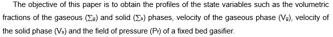
The fluidynamics presented in this paper for a fixed bed gasifier consists of estimating the volumetric fraction fields of gas and solid phases, as well as the velocity fields of gas and solid phases and the pressure inside the fixed bed. However, understanding of the flow characteristics has an important role in knowledge of the operation of the gasifier. The analyzed system consists of the fundamental equations of mass balance for the gas and solid phases, as well as the equations of momentum balance for gas and solid phases and an equation for the pressure given by the sum of the momentum balance equations of the gas and solid phases. The sets of equations developed form a partial differential equations (PDEs) system. The PDEs system has been transformed in a ordinary differential equation (ODEs) system using Laplace Transform. The ODEs system has been solved using an implementation of the finite difference method (FDM). The objective of this work is to obtain the profiles of state variables such as volumetric fractions of gas (εg) and solid phases (εs), the velocity profiles of gas (vg) and solid phases (vs) and pressure field (pf).
Keywords: Fluidynamics, fixed bed gasifier, gas-solid, fuel, Laplace transform, finite difference
1 Introduction
The mathematical models for the gasification systems are important means to project such systems starting from a laboratory scale to industrial scale as well as starting from an existing system extrapolating them to condition one wants to use [1-4]. A good model will help to identify the performance sensibility of a gasification device through variation of different operation conditions and project parameters. Gasification is a conversion of any solid or liquid fuel into an energetic gas through the process of partial oxidation due to elevated temperatures. The process of gasification occurs naturally in four distinct physical-chemical phases with temperatures of different reactions, such as the drying of biomass, devolatization or pyrolysis, reduction and burning [5-8]. Each of these processes can be analyzed in different equipment, depending on the determined sequence by the characteristics of the project.
The technique of gasification is at first, extremely versatile but there are lots of problems in transforming this theoretical potential into a commercially competitive technology, in spite of already being practical and viable [9]. The difficulties lie not in the basic process of gasification but in the project of a device that transforms the solid fuel into a gas of quality with trusty and security adapted to the particular conditions of the fuel and of the operation [10, 11]. In the case of the gases produced being used for electric energy generation the requirements of cleanness of these gases become of extreme necessity due to the sensitiveness of the gas turbines.
The available gasifiers can be classified in two models such as countercurrent flux and co-current flux [12, 13]. The gasifier of countercurrent flux is a device in which the pyrolized biomass and the air enter into different directions, the gas coming out through the upper part. The tars produced during this phase are dragged by the gases that come out from the gasifier [14-16]. The biomass is gasified in the reduction zone using the energy generated in the chemical reactions that occur in the burning zone.
Two phases can be identified in the transversal section of the bed: (i) the emulsion; (ii) the bubbles. The emulsion contains the solid particles and the gas that move (process of the filtering of the gas) through them. The flux of gas in the emulsion is limited by the minimum velocity of fluidization. Any greater amount of gas passes through the bed as bubbles. The bubbles are practically free of solid particles but in its passage through the bed some particles are dragged by them.
2 Direct Problem
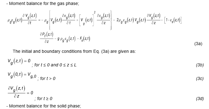
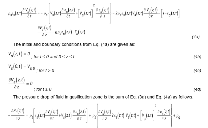
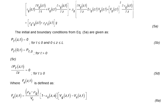
The governing equations of the mass and moment are focused on gasification zone of developed gasifier of this study. From these balance equations, it is possible to obtain parameters that serve to characterize the process that occurs in the gasifiers. The knowledge of these optimized parameters makes the project of the equipment technically viable for an industrial scale. For the development of the model, some hypothesis were considered: (i) the fluxes are one-dimensional, (ii) the fluid phase is compressible, (iii) all the particles have the same dimension; (iv) the irregular movement and the colliding of the particles are ignored; (v) the friction on the wall is ignored. Based on above hypothesis, it has been developed a mathematical model that includes the governing equations of the mass and moment balances limited to its initial and boundary conditions of each model equation as follows.
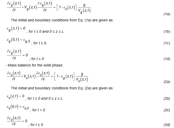
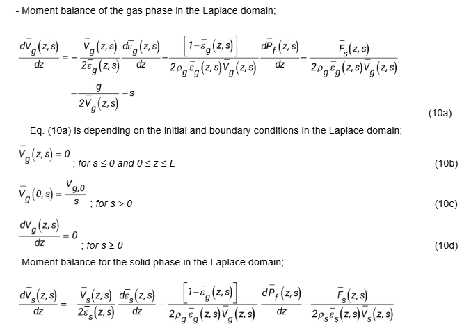
– Mass balance for the gas phase;


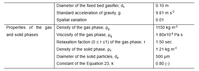
A model validation procedure was established by comparing between the model for the superficial velocity of the gas phase and Srinivasan and Angirasa [20] according to the Fig. (2).
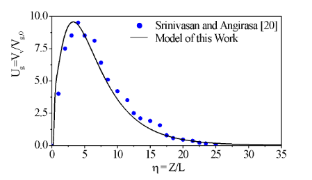
Fig. 2: Comparisons of dimensionless curves for the solution of the model for the superficial velocity of the gas phase.
Fig. 3: Profiles of volumetric fractions in the gaseous and solid phases in the cocurrent fixed bed gasifier versus the axial length (1m) of the fixed bed gasifier.
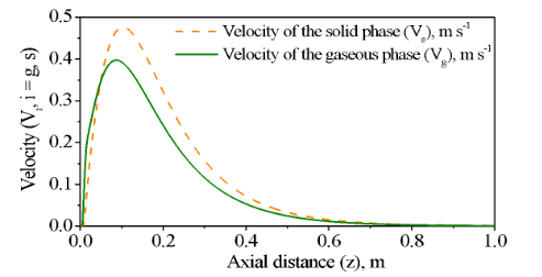
Fig. 4: Profiles of superficial velocities of gaseous and solid phases in the cocurrent fixed bed gasifier versus the axial length (1m) of the fixed bed gasifier.
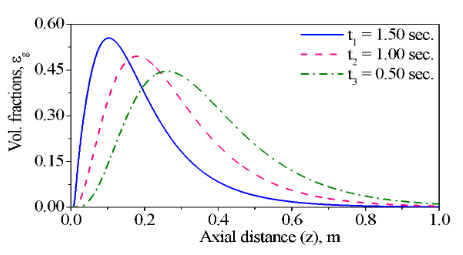
Fig. 5: Profiles of the volumetric fraction in the gaseous phase in the cocurrent fixed bed gasifier versus the axial length (1m) of the fixed bed gasifier using three volumetric fractions (gaseous phase) at the inlet of the fixed bed.
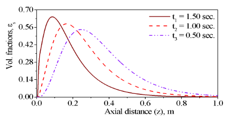
Fig. 6: Profiles of the volumetric fraction in the solid phase in the cocurrent fixed bed gasifier versus the axial length (1m) of the fixed bed gasifier using three volumetric fractions (gaseous phase) at the inlet of the fixed bed.
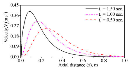
Fig. 7: Profiles of the superficial velocity of the gaseous phase in the cocurrent fixed bed gasifier versus the axial length (1m) of the fixed bed gasifier using three superficial velocities (gaseous phase) at the inlet of the fixed bed.
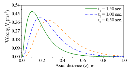
Fig. 8: Profiles of the superficial velocity of the solid phase in the cocurrent fixed bed gasifier versus the axial length (1m) of the fixed bed gasifier using three superficial velocities (gaseous phase) at the inlet of the fixed bed.
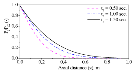
Fig. 9: Profiles of the pressure field in the cocurrent fixed bed gasifier versus the axial length (1m) of the fixed bed gasifier using three superficial velocities (gaseous phase) at the inlet of the fixed bed.
The Fig. (3) shows the profiles for the volumetric fractions in the gaseous and solid phases along the axial distance of the fixed bed gasifier with the physical properties fixed. The Fig (4) presents the profiles of the velocities for the gaseous and solid phases along the axial distance of the fixed bed gasifier with the physical properties fixed.
Figs. (5) and (6) describe the variation for the volumetric fractions of the gaseous and solid phases at different times (t1 = 1.50 sec, t2 = 1.00 sec and t3 = 0.5 sec) with the constant physical parameters. The volumetric fractions of the gaseous and solid phases in Figs. (5) and (6) are initially increasing up to a maximum and then decreasing with the axial distance according to boundary Equations (4) and (8).
Figs (7) and (8) present the variation for velocities of the gaseous and solid phases at different times (t1 = 1.50 sec, t2 = 1.00 sec and t3 = 0.5 sec) with the constant physical properties. Such as in case of the volumetric fractions, the velocities of the gaseous and solid phases in Figs. (7) and (8) are initially increasing up to a maximum and then decreasing with the axial distance according to boundary Equations (12) and (16).
The Fig (9) shows the variation for the pressure field along the axial distance of the fixed bed gasifier with the constant physical properties. This Fig. describes a comparison between three line curves at three times (t1 = 1.50 sec, t2 = 1.00 sec and t3 = 0.5 sec), and as can be seen the pressure field for some z is increasing with respect to time.
4. Conclusions
The modelling of the gas-solid process of the fixed bed was developed in relation to the volumetric fractions (εg and εs) and the velocities (Vg and Vs) as well as an equation for the pressure field resulting from the adding of equations Vg and Vs. The simulations of this model led us to the following conclusions:
– The validation portrayed a satisfactory prognostication for the numerical experiment conducted for the variable Vg;
– It was allowed by the developed model to analyze the sensitivity of the variables εg and εs with the variable t as well as the variables Vg and Vs;
– It was shown by the variables t great influence on the behavior of the fluidynamic variables of the gas-solid process concerning the control of the process in this equipment;
– In this paper, it was performed simulations using only time (t). However, other variables can be tested.
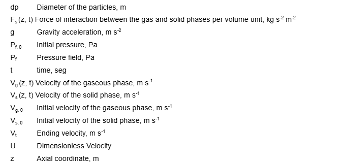
Nomenclature
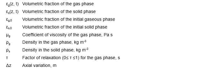
Greek letters
Acknowledgements
The authors of this paper would like to thank CNPQ (National Council of Scientific and Technological Development) for the financial support given. (Process 48354/2017/Project/Title: Computer Modeling and Simulation for the Development of the technology of a Gasification Plant in Combined Cycle for the Generation of Electric Energy./Edict CNPq 15/2017 – Universal).
References
[1] Kim Y J, Lee1 J M, Kim S D (2000) Modeling of coal gasification in an internally circulating fluidized bed reactor with draught tube. Fuel 79 (1): 77 – 69.
[2] Liang Y, Jing L, Xiangping Z, Suojiang Z (2007) Numerical simulation of the bubbling fluidized bed coal gasification by the kinetic theory of granular flow (KTGF). Fuel 86 (5-6): 734 – 722.
[3] Yang Y B, Phan A N, Ryu C, Sharifi V, Swithenbank J (2007) Mathematical modelling of slow pyrolysis of segregated solid wastes in a packed-bed pyrolyser. Fuel 86 (1-2): 180 – 169.
[4] Nemtsov D A, Zabaniotou A (2008) Mathematical modelling and simulation approaches of agricultural residues air gasification in a bubbling fluidized bed reactor. Chemical Engineering Journal 143 (1-3): 31 – 10.
[5] Abdullah M Z, Husam Z, Yin Pong S L (2003) Analysis of coal flow fluidization test results for various biomass fuels. Biomass & Bioenergy 24 (6): 494 – 487.
[6] Arvelakis P, Vourliotis E, Kakaras E, Koukios G (2001) Effect of leaching oh the ash behavior of wheat straw and olive residue during fluidized bed combustion. Biomass & Bioenergy 20 (6): 470 – 459.
[7] Basu P (1999) Combustion of coal circulating fluidized-bed boilers: a review. Chemical Engineering Science 54 (22): 5547 – 5557.
[8] Petersen I, Werther J (2005) Experimental investigation and modeling of gasification of sewage sludge in the circulating fluidized bed. Chemical Engineering and Processing 44 (7): 717 – 736.
[9] Levenspiel O (2002) Modeling in chemical engineering. Chemical Engineering Science 57 (22-23): 4691 – 4696.
[10] Yang Y B, Lim C N, Goodfellow J, Sharifi V N, Swithenbank J (2005) A diffusion model for particle mixing in a packed bed of burning solids. Fuel 84 (2-3): 213 – 225.
[11] Blasi C D (2000) Dynamic behaviour of stratified downdraft gasifiers. Chemical Engineering Science 55 (15): 2931 – 2944.
[12] Gabra M, Pettersson E, Backman R, Kjellstrom B (2001a) Evaluation of cyclone gasifier performance for gasification of sugar cane residue-Part I: gasification of bagasse. Biomass & Bioenergy 21 (5): 351 – 369.
[13] Gabra M, Pettersson E, Backman R, Kjellstrom B (2001b) Evaluation of cyclone gasifier performance for gasification of sugar cane residue-Part II: gasification of cane trash. Biomass & Bioenergy 21 (5): 371 – 380.
[14] Gabra M, Nordin A, Ohman M, Kjellstrom B (2001c) Alkali retention/separation during bagasse gasification: a comparison between a fluidized bed and a cyclone gasifier. Biomass & Bioenergy 21 (6): 466 – 471.
[15] Gómez M A, Porteiro J, Patiño D, Míguez J L (2014) CFD modelling of thermal conversion and packed bed compaction in biomass combustion. Fuel 117 (Part A): 716-732.
[16] Cooper J, Hallett W L H (2000) A numerical model for packed-bed combustion of char particles. Chemical Engineering Science 55 (20): 4451 – 4460.
[17] Mordis G J, Reddell D L (1991) The Laplace transform finite difference method for simulation of flow through porous media. Water Resources Research 27 (8): 1873 – 1884.
[18] Silva J D, Abreu C A M (2012) Mathematical modeling of a three phase trickle bed reactor. Brazilian Journal of Chemical Engineering 29 (3): 567-576.
[19] Oliveira, C. C. B (2012) Fluidynamics modelling of a concurrent fixed bed gasifier with application of the inversion of numerical Laplace transform. Master dissertation, Polytechnic School-University of Pernambuco, Brazil.
[20] Srinivasan J, Angirasa D (1988) Numerical study of double-diffusive free convection from a vertical surface. Int. J. Heat and Mass Transfer 31 (10): 2033 – 2038.
*Polytechnic School – UPE, Laboratory of Environmental and Energetic Technology; Rua Benfica – 455, Madalena, Recife – PE, Brazil, Cep: 50750-470, phone: (81) 3183-7515; Corresponding author: E-mail address: escs2@poli.br