REGISTRO DOI: 10.69849/revistaft/ni10202409081520
Lucas Menezes Viana;
Tulio Henrique Coura
ABSTRACT
This study presents a methodology for maintaining and rebalancing Double Star configuration capacitor banks, which are critical for managing power consumption peaks. As electricity demand is projected to rise by 21% by 2040, efficient maintenance methods are essential to ensure energy security. The paper introduces a novel approach to rebalance capacitor banks using a Matlab application, which simulates the unbalance current that may occur due to capacitive unit failures. Key aspects of capacitor banks, such as construction, connections, and protection methods, were reviewed to inform the methodology.
Capacitor banks are used to control voltage, correct power factor, and reduce losses, but they can experience imbalances due to natural variances in capacitance or failures. The study developed a mathematical model to calculate the unbalance current and validated this model through simulations in LTspice software. The resulting rebalancing flowchart provides a step-by-step guide for technicians to follow during maintenance.
The project achieved its goals, demonstrating through 24 simulations that the developed methodology and Matlab application could successfully predict unbalance currents with a negligible margin of error. The paper concludes that the methodology is ready for implementation, and each capacitor bank will require a tailored rebalancing application based on the presented calculations.
Keywords: Capacitor Bank Rebalancing, Double Star Configuration, Unbalance Current Simulation, Matlab Application for Maintenance, Electrical Power Systems.
1.0 Introduction
The increase in electricity consumption is closely related to economic development in terms of the growth in the industrial sector and demographic evolution. According to the IEA (2021), the energy demand is expected to increase by 21% in 2040, which might mean that the world’s electrical power system will need to receive massive investments and breakthroughs, such as new maintenance methods, to ensure energy security for society. This could include, but not be limited to, the acquisition of equipment, the creation of new transmission lines, the construction of new substations, and new power plants, among others.
An electrical power system is formed by different materials, components, and equipment that, together throughout the system, ensure quality energy delivery. The most significant electricity consumption time, generally between 6 pm and 9 pm, is characterized by a highly inductive load profile. This profile is recognized for causing a lower voltage level, an increase in the flow of reactive power in the lines and a drop in the power factor of the electrical system. To mitigate these effects and adapt the system to the conditions pre-established by regulatory agencies, electricity distribution companies such as BC Hydro and Fortis BC use a bank of shunt capacitors installed at strategic points throughout the electrical network.
According to Beaty and Fink (2012), the main benefits of using capacitor banks are as follows: a) voltage control;
a) power factor correction;
b) increase in network capacity;
c) reduction of losses;
d) reduction of energy consumption.
Despite the broad operational advantages, it is necessary to pay attention to some constructive and operational problems of the system so that capacitor banks can operate, promoting the reported benefits. Essentially, capacitor banks are formed by several capacitor units configured in seriesparallel so that the set of units configures the banks in typical star, delta and H-bridge connections.
Capacitor units are manufactured to have a nominal capacitance value within an established range. For shunt power capacitors connected to nominal voltage systems above 1000 V, the subject of this work, the measured capacitance must be between the limits 0% to +10% of the nominal capacitance of the unit plate (IEEE 18-2012).
Based on this regulation, it is reasonable to assume that capacitor banks have an inherent unbalance due to the plate capacitance value of capacitor units varying within a range of values. The natural unbalances, linked to the unbalance of supply voltages and failures in the banks, such as the loss of capacitor units over time due to dielectric failures, generate the circulation of a permanent current in the neutral point of the banks. This current is monitored by a protection system responsible for issuing alarms or disconnecting the capacitor bank due to variations outside the acceptable limits.
The operation of this protection, called Unbalance Protection, indicates the occurrence of failures and overvoltage at the terminals of the bank’s capacitor units. Given the circumstance, the bank’s balance may be compromised. The maintenance team must perform the replacement of the damaged units. Although it seems simple, replacing capacitors requires a thorough study that leads to a methodology capable of rebalancing the bank within adequate adjustments.
Therefore, developing a method capable of rebalancing capacitor banks, proposed in this work, might be essential to the energy concessionaires to ensure exemplary performance at times of high demand. This can also be a vital factor in guaranteeing the quality of the electricity delivered to consumers in the next 19 years with huge savings due to optimizing the maintenance processes that can reach around 15% per year of savings (Blooming & Carnovale, 2007).
2.0 Goals
2.1 Main Goal
To introduce a methodology for rebalancing a capacitor bank with a Double Star connection, neutral – not connected through an App in Matlab software.
2.2 Complementary Goals
a) Present the main constructive elements of capacitor banks;
b) Develop a mathematical model to obtain the unbalance current;
c) Improve the accuracy in determining the unbalance current;
d) Increase assertiveness in rebalancing a capacitor bank through an App in Matlab software.
3.0 Methodology
In order to create the methodology for rebalancing a capacitor bank in the Double Insulated Star configuration, related works are examined, and a bibliographical review is conducted through books, magazines and articles on constructive aspects, connection types and protection models of the capacitor banks.
A mathematical model is developed to obtain the unbalance current measured by the bank’s protection system by the laws of electrical circuits, such as Kirchhoff’s and the star-triangle transformation (Y-Δ).
Simulations in the LTSPICE circuit software will enable the capture of different waveforms. For a practical demonstration, the authors assume bank documents such as the Capacitance Map, the nominal operating voltage, the nominal power, the type of connection and the unbalance protection calculation based on the paper’s studies and previous job experience with power capacitor banks.
4.0 Assumptions
The assumptions related to this paper are essential to the project’s success due to the need for more information related to some confidential parameters, such as the unbalance protection study, architecture and layout of the capacitive units. Access to this information is confidential, requiring permission from a capacitor bank manufacturer or a utility company such as BC Hydro or Fortis BC, which is not the case in this paper. Therefore, the considerations written above were based on the author’s literature review and previous job experience with the theme.
a) Capacitive units with internal fuses protection;
b) Unbalance protection by neutral current;
c) Unbalance Current (ID – alarm) = 1.5 A;
d) Unbalance Current (ID – trip) = 2.3 A;
e) Ideal protection system (no losses).
5.0 Literature Review
Concepts are reviewed about the constitution of power capacitor banks, such as the constructive and technological aspects of the capacitive units, types of connections and models of protection. It is essential to know these theories to elaborate on a reliable methodology capable of rebalancing shunt capacitor banks.
5.1 Basic concepts about capacitors
The correct functioning of the capacitor banks depends on responsible maintenance by ensuring good performance to extend their useful life. Among these measures, knowing the basic theory about capacitors is the start to adopt a method to rebalance capacitor banks after faults in the capacitive units occur.
5.1.1 Capacitor construction
Capacitors are made of two parallel conducting plates separated by an insulating material. When the plates are subjected to a potential difference, an electric field is generated between them (Boylestad, 2012). Figure 1 presents the distribution of field lines considering the edge effect, which can be neglected for most applications and the ideal capacitor.
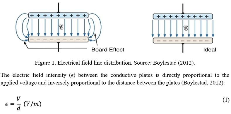
The capacitance corresponds to measuring the amount of charge the capacitor can store. In other words, the greater the capacitance value, the greater the charge storage capacity and, consequently, the greater the electric field intensity between the plates. The capacitors’ measurement unit is the farad (F) (Boylestad, 2012).
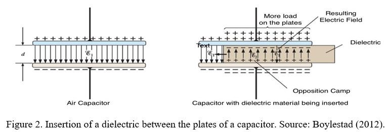
Another critical property of dielectric materials is their dielectric strength. This property establishes the maximum potential that can be applied under the area of the insulating material. Dielectric strength is measured in volts/mm. The rubber has a dielectric strength equal to 27×10³ V/mm. Suppose a working voltage, called breakdown voltage, is established to break the dielectric strength. In that case, the insulating material loses its dielectric properties, and the capacitor behaves similarly to a conductor (Boylestad, 2012). In the design of capacitors, the dielectric strength of the insulating material used typically defines the maximum working voltage.
5.1.2 Connection of capacitors
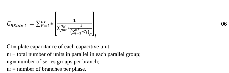
The capacitors can be associated in the electrical circuit in series or parallel (Beaty & Fink, 2012). The series association of a set of capacitors is defined as shown below in equation 03:

Ce – Equivalent capacitance of series capacitors.
C1, C2, C3…Cn – Nominal capacitance for each capacitor in the set.
The parallel association of a set of capacitors is defined by equation 04 as follows:

5.2 Power capacitors
The first power capacitors were used in the mid-1910s in the industrial sector. These devices were made of paper impregnated with wax, constituting the dielectric material. In addition, they were heavy, large, and expensive (Beaty & Fink, 2012). The technology employed, mainly in the manufacture of insulating material, provided significant active losses, making unfeasible the use of capacitors for power factor correction in the industrial sector. However, technology has evolved over the years, resulting in reduced losses and increased yield, reliability, and safety in capacitors (Boylestad, 2012).
5.2.1 Capacitive power unit
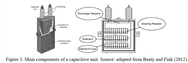
A capacitive unit is composed of several capacitive elements configured in series-parallel to provide adequate reactive power (VAr). The capacitive unit has other features such as the terminal connector, bushings, steel case, discharging resistor and element fuse. This set constructively configures the power capacitor (Beaty & Fink, 2012). Figure 03 presents a capacitive unit with its respective components.
5.2.2 Capacitive elements
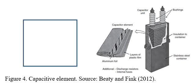
The manufacturing process of capacitive power elements is carried out by winding thin layers of solid dielectric (polypropylene) with thin aluminum sheets, constituting the electrodes (Beaty & Fink, 2012). Figure 04 shows a typical power capacitive element.
In order to improve the insulation of capacitive elements, the capacitive units are impregnated with insulating liquid. Until the mid-1970s, the units were impregnated with insulating oil known as Askarel. Despite presenting excellent dielectric characteristics, it was banned from use due to the presence of harmful substances that could cause cancer in humans (Beaty & Fink, 2012). Nowadays, impregnation is done with synthetic oil belonging to the family of aromatic hydrocarbons such as Faradol and Indol II (ABB, 2013).
5.2.3 Protection for capacitive units
Linked to the disposition of capacitive elements is the technology deployed to protect individually each capacitive unit, which can be formed by internal or external fuses or without fuses (fuseless) (ABB, 2013). Figure 05 represents what has been described.
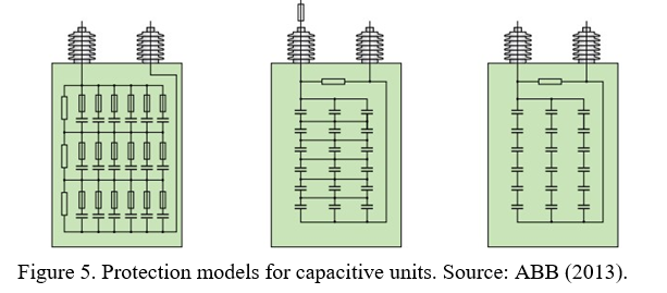
These configurations follow a technological evolution through the pioneering of external fuse protection, internal fuse protection, and the most recent, used by some electric power utilities companies, the fuseless protection (ABB, 2013).
Among the configurations described, the protection of capacitors by internal fuses is currently the most adopted by electric power utilities (Panda & Pachpund, 2021). The capacitor bank, which will be the subject of this study, is assumed that has capacitive units with internal fuse protection.
Internal fuse protection is characterized by each capacitive element being protected by a fuse connected in series with the element. In the event of a dielectric failure, the fuse acts and isolates only the defective element, generating a slight variation in the nominal capacitance of the unit (ABB, 2013). Figure 06 shows a capacitive unit with defective elements.
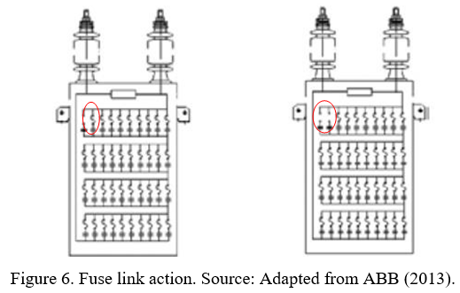
The main disadvantage of this protection model is the difficulty in locating the faulty unit through simple visual inspection. Despite this significant disadvantage, it is worth noting this technology’s several operational advantages (Kasztenny & Samineni, 2003).
a) higher operational availability of the bank;
b) lower power loss in the occurrence of dielectric faults;
c) greater ease in adjusting the bank’s unbalance protection;
d) low probability of unintended fuse operation;
e) fewer spare units required;
f) smaller area required for bank installation.
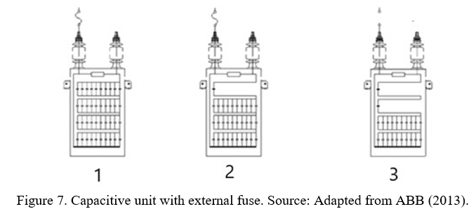
External fuses protect the capacitive unit through a fuse connected in series with one of the unit’s terminals. Unlike internal fuse protection, in the event of a dielectric fault the protection removes the entire capacitive unit, causing a significant variation in the bank’s capacitance. However, the great advantage of this protection model is that it is possible to locate the faulty unit through a simple visual inspection by the maintenance team (ABB, 2013).
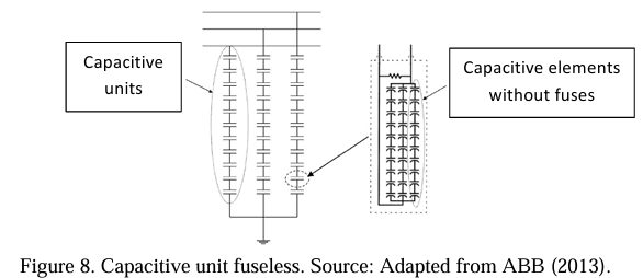
Despite the conservatism of electricity concessionaires in adopting protection through external or internal fuses, the preference for fuseless protection has been growing (Kasztenny & Samineni, 2003). This technology is based on the high quality of the insulating material used to manufacture the capacitive element. When a short circuit occurs in a capacitive element, the aluminum leaves a fuse, generating an electrical connection (ABB, 2013).
5.2.4 Discharge resistor
The discharge resistor is a critical component, especially regarding the safety of people who work with capacitor banks. When the bank is disconnected, the resistor converts the stored energy into Joule losses, reducing the voltage to low levels in a specific time interval (Beaty & Fink, 2012).
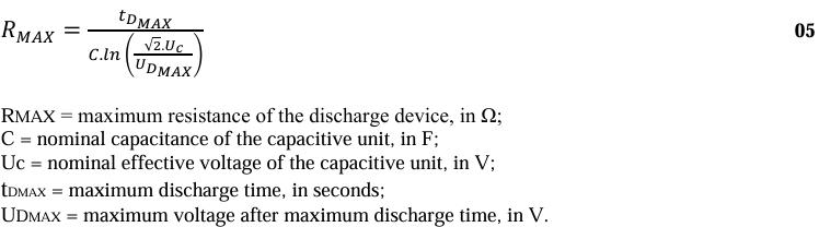
IEEE (2013) establishes that, after 5 minutes of disconnection, the voltage measured between the unit terminals must be less than 50 V. To calculate the value of the discharge resistor, Equation 05 is shown below (IEE, 2013).
5.3 Types of capacitor bank connections
Shunt capacitor banks can be connected in delta, a single or double star, and H-bridge configurations. Among these connections, some variations may occur due to planning and system requirements. These variations include grounded or isolated single-star, grounded or isolated double-star, and H-bridge star or delta. According to Kasztenny and Samineni (2022), the adoption of one of these configurations depends mainly on the following factors:
a) voltage and power of the bank;
b) operating voltage and grounding type of the system;
c) construction and technological aspects of the capacitor units;
d) protection philosophy to be implemented.
In addition, these connections have an economic difference that weighs the definition of the arrangement to be adopted. Therefore, it is necessary to analyze the advantages and disadvantages of each configuration in order to make the best choice. Figure XX shows the connection diagram for some of these configurations.
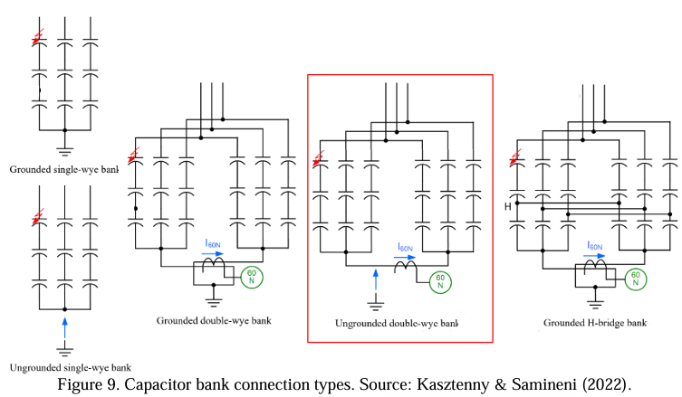
This work discusses all general aspects of the Ungrounded Double Star (wye) configuration, as it aims to adopt a rebalancing methodology for a capacitor bank in this type of connection. However, the other configurations are widely used. Therefore, the authors believe that this work will serve as a basis for developing different rebalancing methodologies in the future for other configurations.
5.3.1 Double star connection – neutral, not connected
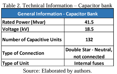
This type of connection is typically used in large capacity banks with many capacitive units (Panda & Pachpund, 2021), as is the case of the capacitor bank that will be studied in this work, which is assumed to have 132 capacitive units.
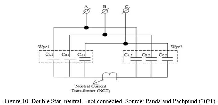
The arrangement of the Double Star, neutral – not connected capacitor bank facilitates the adjustment of the unbalance protection since the system is immune to the natural unbalance of the power supply system. In addition, transient currents, such as energization (inrush), have lower amplitudes when compared to banks with grounded neutral (Panda & Pachpund, 2021). However, the isolation of the neutral can increase the cost of the bank’s design since it must be isolated for phase-to-phase voltages of the system. These values are high for Double Star Isolated banks whose operation is performed with a nominal voltage above 15 kV (Compton, 1955).
Another aspect of this capacitor bank model, which is highly relevant, especially for this work, is the difficulty of establishing a mathematical model to obtain the value of the unbalance current measured at the common point between the two stars. It occurs due to the neutral displacement generated by the natural unbalance between the capacitances of each star. In other words, the fact that the neutral is isolated generates a natural unbalance between the phases that make it impossible to determine the magnitude of the voltage applied to each equivalent capacitance of the bank (Compton, 1955). Therefore, a model will be necessary for calculating the unbalance current and will be presented in section 6.0 of this paper.
5.4 Capacitor bank protection
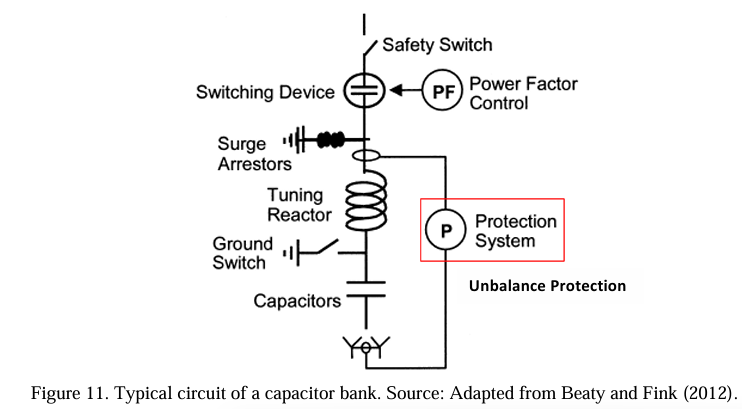
Capacitor banks are susceptible to external interferences, such as transient overvoltage and internal faults. In order to monitor these interferences, capacitor banks have protection systems for external and internal faults. The protection against external faults has the function of monitoring and preventing events such as external arc, overvoltage, overcurrent, and loss of bus voltage, which can cause irreversible damage to the bank (Brunello, 2003). This protection is provided by overcurrent relays (50/51), neutral overcurrent (51N), overvoltage (59B), and Undervoltage (27B), whose primary function is to send a command to open the breaker (52) in case of occurrence (IEEE, 2013b).
In addition to relays and circuit breakers, a typical capacitor bank circuit includes disconnect switches, lightning arresters, reactors and measurement transformers (Beaty & Fink, 2012). Figure 11 shows a typical capacitor bank circuit.
Protection against internal events, known as unbalance protection, is considered exclusive to capacitor banks and of utmost importance. This protection supervises the operational conditions of each capacitive unit that makes up the bank. During the operational life of the bank, internal failures can occur in such a way as to render one or more capacitive units inoperable or even cause the explosion of a capacitive unit due to the burning of capacitive elements (Brunello, 2003).
A capacitor bank formed by capacitive units with internal fuse protection, which is the theme of this project, has an unbalance protection system that aims to monitor the failure of each capacitive element of the unit (Brunello, 2003). The actuation of a particular capacitive unit’s internal fuses results in the removal of the defective capacitive element, thus generating a variation in the unit’s nominal capacitance. Additionally, there is a voltage redistribution in the unit’s remaining capacitive elements, leaving them subject to permanent overvoltage (Kasztenny & Samineni, 2022). IEEE (2013b) establishes that capacitive units can operate for a continuous period of 12 hours with permanent overvoltage, provided that it does not exceed 110% of the nominal voltage in any capacitive element of the unit.
The unbalance monitoring system can be performed by current or voltage sample. The configuration under study allows for establishing the two unbalanced monitoring models, as shown in Figure 12. Although the configuration allows for both models, the most widely adopted model consists of monitoring by neutral current, which will be considered in this project (Panda & Pachpund, 2021).
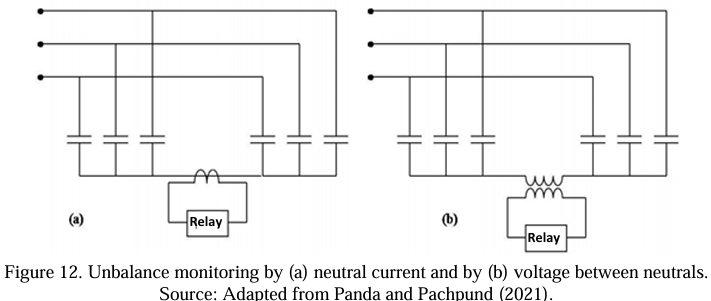
Therefore, the calculation model developed in this work will be designed for a capacitor bank in the Double Star configuration, neutral – not connected with a monitoring system by the neutral current. It is worth noting that the protection aspects for capacitor banks briefly discussed in this section aim to present a general idea of the importance and functionality, especially of unbalance protection.
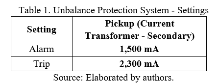
The critical parameters for this work are the values set by the protection engineer for the maximum unbalance current that can flow through the neutral point of the double star. It will be the main criterion for comparing the effectiveness of bank rebalancing. Therefore, Table 1 presents the parameters assumed for this project. Furthermore, the project considers the protection system ideal, which means no losses throughout the system.
5.5 Capacitor bank balancing
6.0 Development of the calculation method and procedures
This chapter presents the technical data and main characteristics of the capacitor bank under study. Furthermore, the calculation development to obtain the unbalance current, automation of the mathematical development in Matlab and description of the functioning of the rebalancing worksheet are described.
6.1 Capacitor bank general information and documents
In order to carry out the rebalancing, it is necessary to access and evaluate two documents from the bank, the Capacitance Map and the Unbalance Protection Calculation. For this work, the authors are applying assumptions based on their prior knowledge of the subject.
It is essential to emphasize that in order to access accurate capacitor bank documentation, it is necessary that a respective energy utility or manufacturer, such as BC Hydro or Fortis BC, provide access to the data, which is not the case in this study that aims to present a rebalancing methodology for a generic capacitor bank.
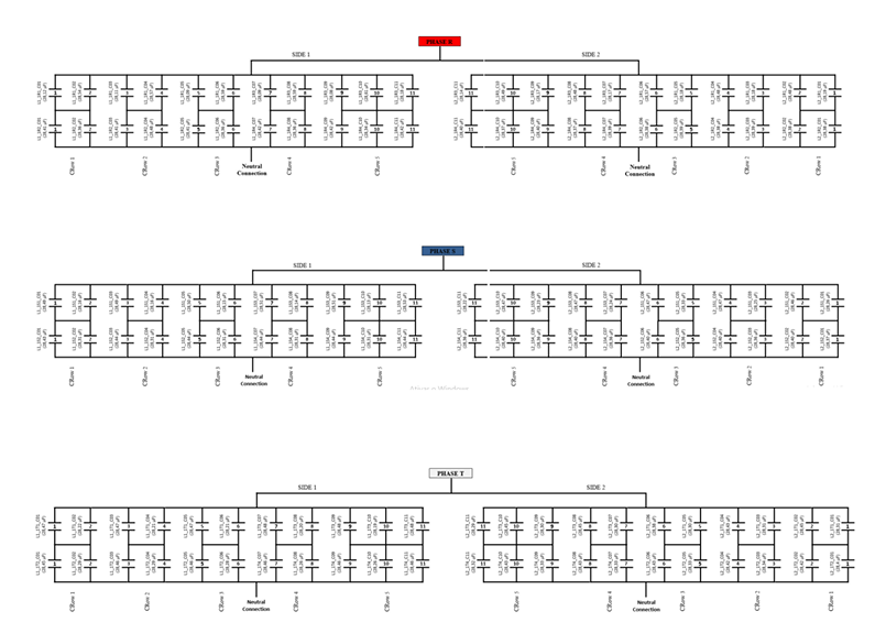
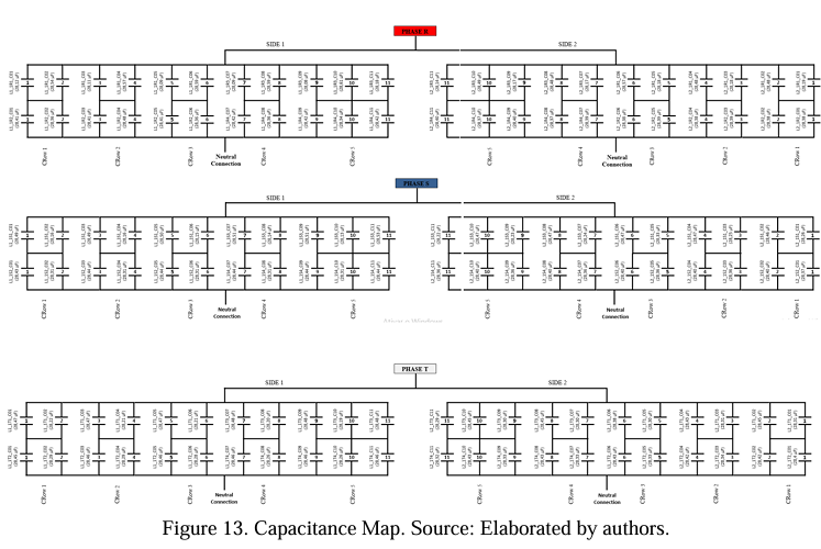
The Capacitance Map includes the primary operational information of the bank, such as nominal power and voltage, number of installed capacitive units, capacitive unit model, type of configuration and, mainly, the disposition of the capacitive units with the capacitance value.
The Unbalance Protection Calculation shows the study to obtain the protection set points: alarm and trip level (bank shutdown). In this case, 1.5 A (alarm) and 2.3 (trip) values are assumed. Below is a clarification of parts of the documentation.
Another essential information from the Capacitance Map is the address of each capacitive unit. The address is used to locate the failure unit and then proceed with the necessary simulations to find the best spare unit to enter into operation. Figure 15 shows the address of a capacitive unit.
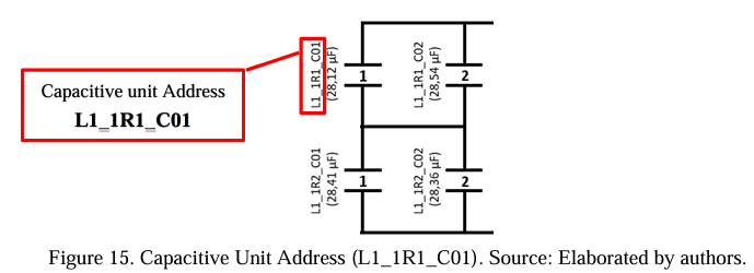
Table 02 presents the technical summary data of the capacitor bank assumed by the authors.
6.2 Mathematical development of the unbalance current
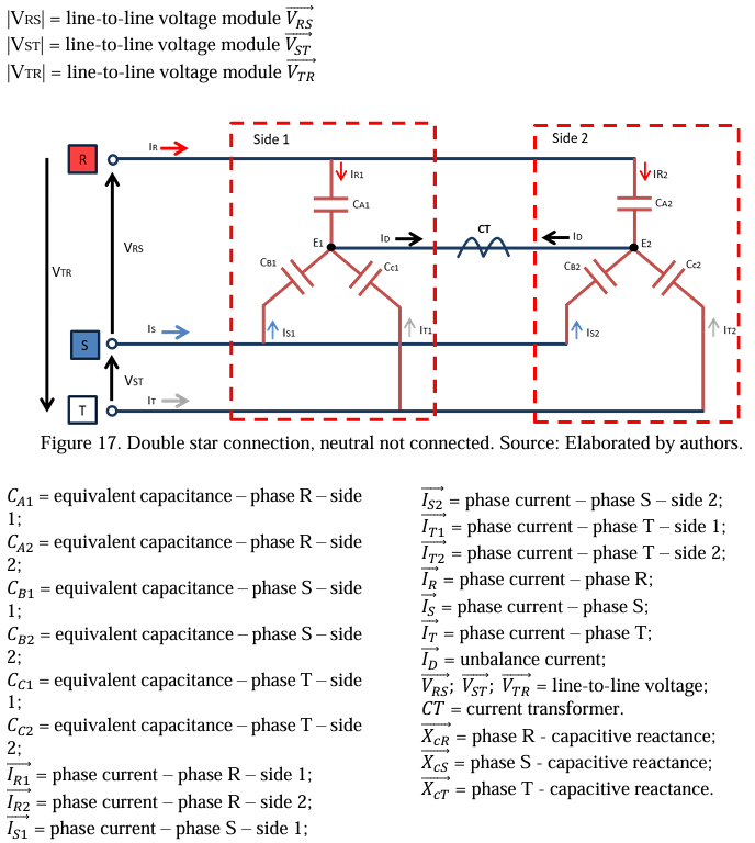
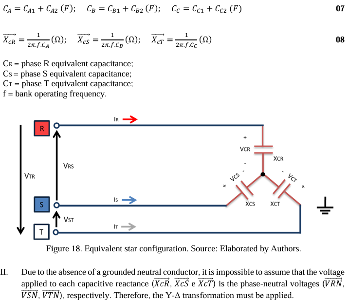
In this section, calculations are developed to obtain the magnitude of the unbalance current (ID) measured by the capacitor bank’s unbalance protection system (CT) between the common points E1/E2 of the double star. The current value is essential to validate the rebalancing of the capacitor bank, as shown below in Figure 16.
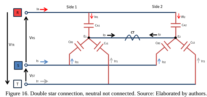
For the circuit in question, some considerations are necessary:
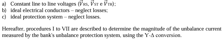
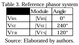
Before starting the first calculation stage, it is necessary to establish a reference phasor voltage system and present the variables of the electrical circuit. Table 3 describes the phasor system to clarify the preliminary steps.
The procedures from I to VII to obtain the unbalance current (CT) are described below:
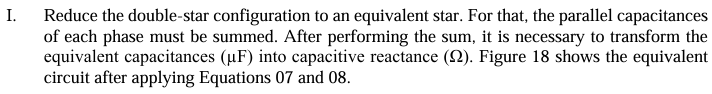
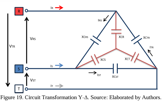
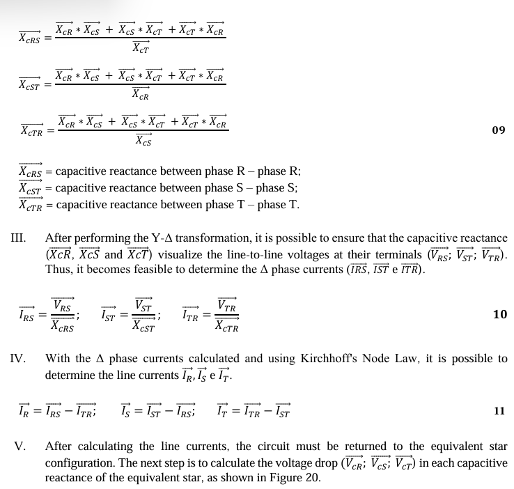
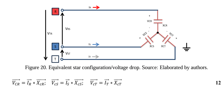
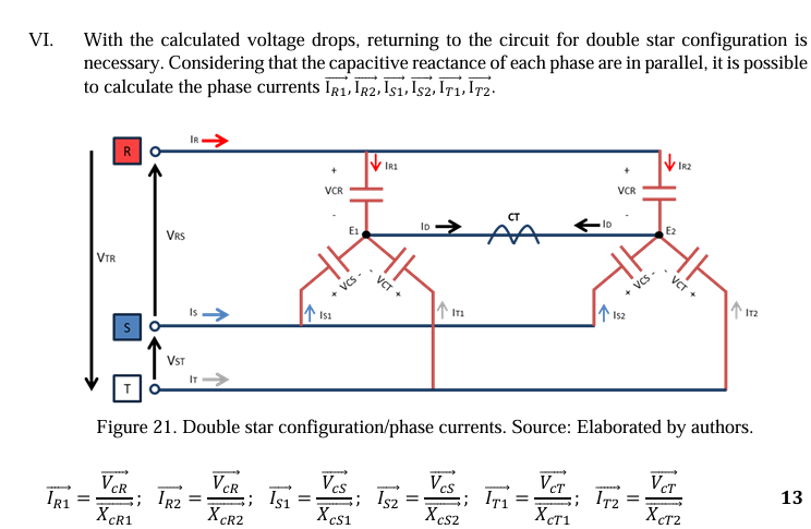
VII. Finally, it is possible to determine the unbalance current being measured by the bank protection system (CT). In the last step, Kirchhoff’s Law of Nodes is applied on one side of the star to obtain the unbalance current value (ID).

6.3 Development in Matlab – Algorithm
The automation of mathematical development is essential to rebalancing the capacitor bank. It makes it possible to follow the changes in the unbalance current value (mA) in case of necessity to change capacitor units due to operational failure.
Based on that, the Matlab software presents itself as a suitable computational tool for this purpose, as it is an accessible software for educational scope. In addition, it enables the creation of an app installation file that can be shared with any user with a Windows operating system or IOS, with no need to obtain Matlab, which has a paid license.
The automation process in Matlab is implemented according to the mathematical development presented in subsection 6.2. The entire programming step-by-step followed the flowchart in subsection 6.2.1. In the end, the installation file was named “FinalProject_NYIT.”
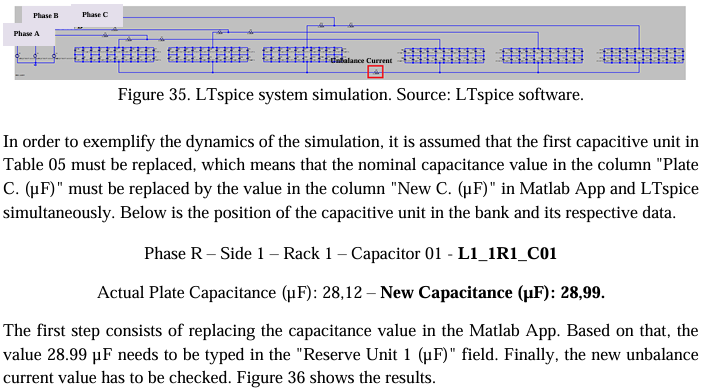
The difficulty in programming the mathematical development was due to the need to work with algebraic variables, such as the variable that identifies the location of the damaged capacitive unit. In theory, the software was not designed to work with magnitudes of this nature. Therefore, manipulations were made by the authors in order to solve the issues and then determine the unbalance current. In order to guide the user and present the layout and resources available in the App, a contingency scenario is proposed.
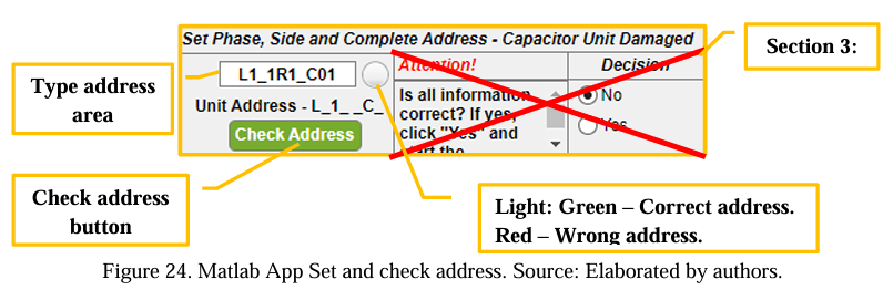
After commissioning the capacitor bank, it is assumed that the measurements verified a capacitor unit with the address (L1_1R1_C01) – phase R, side 1, rack 1, capacitor C01 presented an internal capacitance variation of 10%. Given this, it is necessary to remove the unit from service.
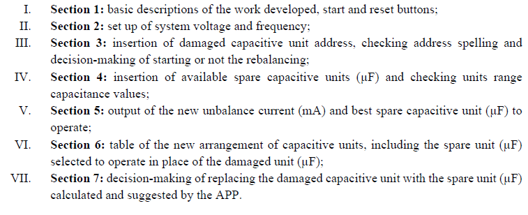
It is worth mentioning that the bank unbalance protection is configured for 1.5 A – alarm level and 2.3 A – trip level. To solve the problem, the technician responsible for rebalancing the bank must open the Matlab App and start the simulations to find the best spare capacitor unit that keeps the bank’s unbalanced current lower than 1.5 A (alarm level). The App user interface was divided into seven sections, as presented in Figure 22 and explained below.
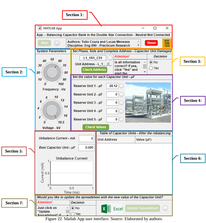
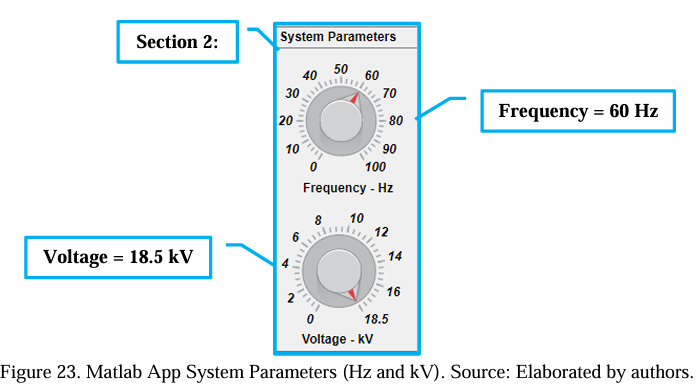
After opening the App, the user must start the rebalancing procedure through section 2. The value of phase-to-phase voltage (kV) and operation frequency (Hz) must be set. It is fundamental to mention that the App starts with the assumed values of 60 Hz and 18.5 kV. If the values remain the same, no changes are required, and the user can move to section 3.

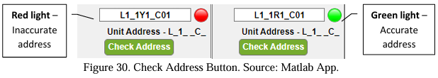
After that, it is necessary to check through the “Check Address” button if the address spelling is accurate. Thus, after clicking the button, if the light becomes green, it means the address was appropriately typed, but if it becomes red, it means something has been miswritten. The user needs to verify before starting the rebalancing.
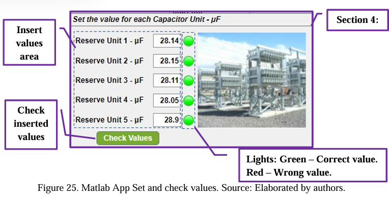
Following the steps, five spare capacitive units are assumed in the substation stock. Thus, inserting the values in the App to calculate and provide the best backup capacitive unit to enter into operation is necessary. Table 4 shows the data for the five backup capacitor units.
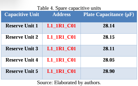
The values of all five options must be entered into the “Step 4” field. After that, it is time to check through the button “Verify Values” if the inserted values are between +/- 30% concerning the value of the capacitive unit to be changed.
After clicking the button, the values were appropriately typed if the light becomes green, but if it becomes red, it means something has been miswritten. The user needs to verify before starting the rebalancing.
After inserting and checking the information, considering that everything is accurate, the user needs to go back to step 3 – “decision field” to select the option “Yes” to finally click on the button “Start” in the “menu section” to start the simulation.
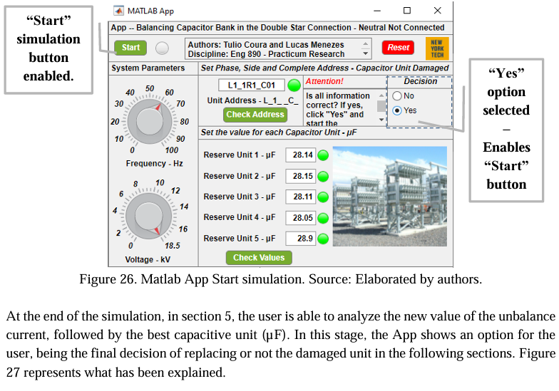
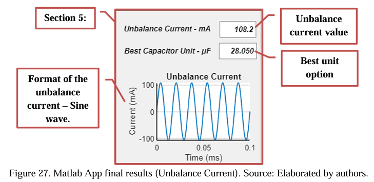

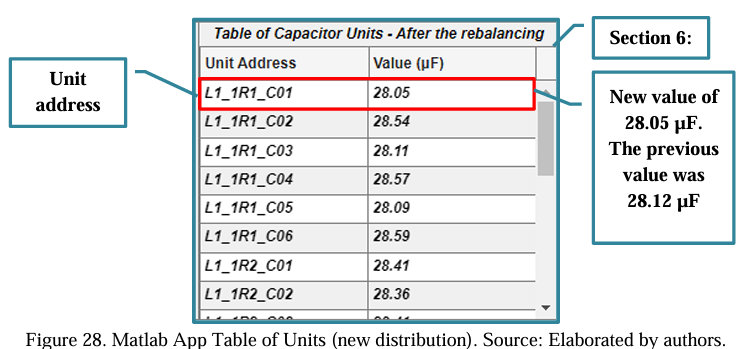
After these steps, the technician responsible for the rebalancing needs to consider whether or not to replace the faulty unit with the one suggested by the App. Section 6 presents the new distribution of capacitive units, considering the newly selected unit. Figure 28 shows the distribution.
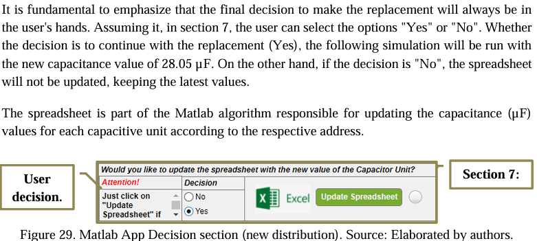
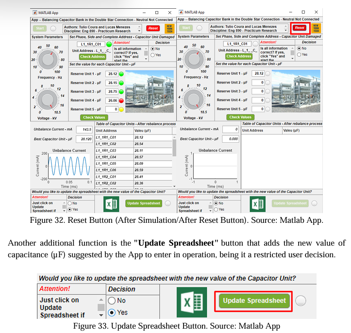
In addition, in case of the user decides not to continue with the replacement, in section 1, there is the button “Reset” that might be used to clear all the current information without establishing the update. These extra functions will be better explained in subsection 6.2.2.
In case of the unbalance current does not reach acceptable values, which means an unbalanced current below 1.35 A, it is necessary to carry out an analysis for relocation of capacitive units of the bank. This analysis is challenging, as it requires heuristic knowledge from the technician responsible for the rebalancing.
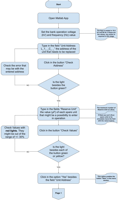
6.3.1 Flowchart for capacitor bank rebalancing
A flowchart was prepared to group the appropriate process for using the Matlab App, which summarizes step-by-step what the user has to follow. For the user to successfully rebalance the bank, it is necessary to have the capacitor bank documents, such as the Capacitance Map, the Unbalance Protection calculation, and the flowchart.
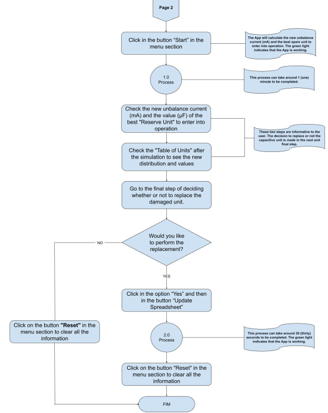
6.3.2 Additional functions of the App for the user
In order to minimize the probability of typing errors by the user, the App generates some indications to alert and not allow the entry of inconsistent data. If any inconsistencies described below are displayed on the screen, the user must check the respective information before starting any simulation.
The “Check Address” button analyzes whether the typed address for a respective unit follows the standard established. In subsection 6.3, it is possible to understand in detail the standard mentioned. In case of any mistake, the light beside the button will become red, which means the user has committed a mistake. Thus, the information must be verified. However, if the light becomes green, the information is accurate.
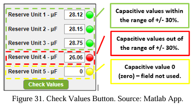
The capacitance values (X) of reserves units have been configured to be within a range of 30% considering the unit that needs to be replaced, which is [X – (X*30%) < X < X + (X*30%)]. Therefore, all the values typed in the field “Reserve unit” must be within this range.
An exception is 0 (zero), meaning the user will not use a respective field. This situation might happen when the user has less than 5 (five) spare capacitive units to be simulated. The green light indicates an accurate value, a red light represents a typed value out of the range that needs to be fixed, and the yellow light suggests a field that will not be used (value 0 (zero)).
The “Reset” button was created to clear any pending errors or simulation that has been done. It brings the App to the standard condition. Figure 32 illustrates what has been described.
7.0 Simulations
This chapter addresses the simulations performed in the LTspice computational environment. The purpose of the simulations is to validate the mathematical development presented in subitem 6.2. For this, the capacitance value of 24 units was randomly replaced in both software. In other words, the simulations intend to compare the value of the unbalance current obtained in the LTspice software and the Matlab App.
7.1 Description of the simulated system
The simulations consider a generic capacitor bank from a 500 kV substation. In this bank, each side of the double star has five series groups, and each group is divided into subgroups with capacitive units in parallel. There are four series groups with two capacitive units in parallel per subgroup and one series group with three capacitive units per subgroup. Figure XX represents the bank.
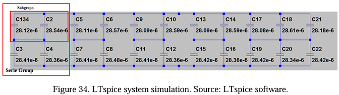
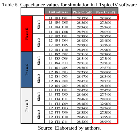
Given the system, the authors chose 24 (twenty-four) arbitrary capacitive units from the bank, being at least 4 (four) units on each side of the double star. Below is a table with the address data, real plate capacitance value, and capacitance value to be replaced.
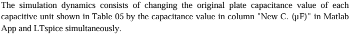
After that, the intention is to compare the value of the unbalance current obtained in the Matlab App and the LTspice software. The Capacitance Map document was used to design the capacitor bank configuration in the LTspice software with all 132 capacitive units. The unbalanced current is measured through a low-impedance resistor connected at the common point of the two stars. Figure 35 shows what has been described.
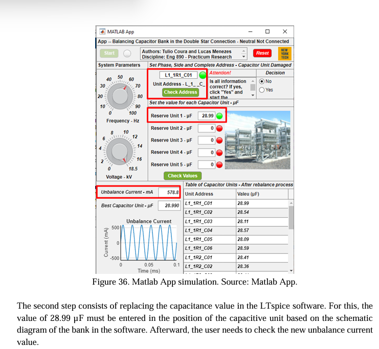
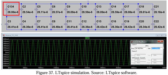
After the simulation, it is possible to compare the current values found in the Matlab App (ID = 578.80 mA) and the LTspice software (ID = 573.2256 mA). Comparing the values shows total convergence, with a minimum error of 5 mA or 0.95%. This process proves the veracity of the mathematical development presented and programmed in the Matlab App.
7.2 Simulation results and analysis
Subitem 7.1 presented the simulation dynamics and the result obtained for replacing 1 (one) capacitive unit. Table 06 below was created to complement the simulation process, which simulates 24 (twenty-four) unit replacements.
This table shows the results obtained in the 24 (twenty-four) simulations carried out simultaneously in the Matlab App and the LTspice software. In this simulation step, there was no concern about verifying whether the value obtained for the unbalance current was within the desired and acceptable adjustments by the unbalance protection system. It means that the attention was restricted to verifying the convergence between the value obtained in the App and the software.
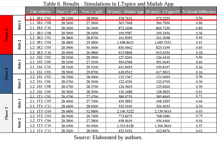
The simulations were essential to prove the feasibility of the mathematical development programmed in the Matlab App. In all simulations, it is possible to verify the proximity between the values obtained in the App and the software for the unbalance current.
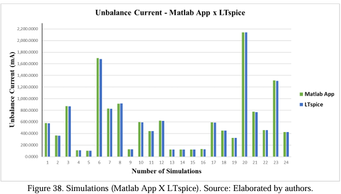
The comparison between the values obtained can be seen in Table 06 through the columns “ID (mA) – Matlab App” and “ID (mA) – LTspice.” The first simulation found the most significant variation, where the difference between the value obtained in the Matlab App and the software was 0.96% or 5.53 mA. This difference can be considered negligible due to a convergence error in the software’s calculation. In order to present the difference between the values obtained for each simulation, the graph below was prepared.
8.0 Conclusion
This project aimed to present a maintenance methodology to ensure an adequate rebalancing of a capacitor bank in the Double Star configuration, neutral – not connected. The entire study was based on virtual monitoring of the unbalance current, which means that before the bank is put into operation, there is an idea of the possible value of the unbalance current. Virtual monitoring was possible due to mathematical development elaborated and automated in the Matlab software. In the end, a rebalancing flowchart was created that includes all the necessary steps for the responsible technician to rebalance the bank in case of capacitive unit failures.
In order to achieve the outlined objectives, capacitor banks’ main constructive and technological aspects were evaluated, such as the constitution of the power capacitor, main characteristics of capacitive units, types of connection, and the way of performing capacitor bank protection. Several peculiarities of capacitor banks that were studied directly affect the rebalancing. In order to exemplify, can be cited the protection technology used in the capacitive unit: external fuse, internal fuse, or fuseless. This characteristic is of utmost importance since it determines the degree of variation in the internal capacitance of the unit due to dielectric failure. Another essential characteristic is the unbalance protection model, which can be by a current or voltage monitoring sample.
Initially, there was difficulty in establishing an adequate calculation model to determine the unbalance current due to neutral displacement caused by the difference between the nominal capacitance values of the bank. In order to overcome the problem, it was necessary to establish a calculation step in which the star-delta (Y-Δ) transformation was applied.
After the elaboration of the mathematical development for determining the unbalance current, the next step was to automate the calculation. For this purpose, Matlab software was used. The software was chosen due to its easy access and manipulation by any user in the technical engineering field, as well as users that do not have access to the software but can install the App through the executable file. The entire rebalancing procedure and App manipulation were summarized in a flowchart. Thus, to rebalance a capacitor bank in the Double Star connection, neutral – not connected, follow the step-by-step “Rebalancing Flowchart.”
The mathematical development and the Mat App implementation were validated through simulations carried out in the LTspice software. The simulations were conducted by simultaneously changing the nominal capacitance value of capacitive units in the Matlab and LTspice software. After that, comparisons were made to verify the convergence between the values obtained. Twenty-four (24) capacitance unit substitutions were executed. The first simulation verified the most significant variation, where the difference between the value obtained in the Matlab App and the LTspice software was 5.53 mA or 0.96%. This difference is negligible and can be attributed to a calculation convergence error in the software itself. A graph was elaborated to present the variations for the 24 proposed simulations.
Therefore, based on the studies conducted and the elaborated, tested, and proven rebalancing procedure, it can be affirmed that all the objectives outlined for this project were achieved. The use of the final product developed by the concessionaires depends only on the implementation and testing in real contingency cases in capacitor banks. It is worth noting that for each capacitor bank, it is necessary to develop a rebalancing App. The developed calculation can be applied to any capacitor bank in the Double Star connection, neutral – not connected.
References
ABB. (2013). ASEA BROWN BOVERI, ABB. Power capacitors and harmonic filters: buyer’s guide. Available at: https://rb.gy/tdubyd
Beaty, H. W., & Fink, D. (2012). Standard Handbook for Electrical Engineers (16th ed). McGraw-Hill Education.
Blooming, T. M., & Carnovale, D. J. (2007). Capacitor Application Issues. IEEE Conference Record of Annual Pulp and Paper Industry Technical Conference. https://doi.org/10.1109/papcon.2007.4286298.
Boylestad, R. L. (2012). Introduction to circuit analysis (12sd ed). Pearson Prentice Hall.
Brunello, G. B. (2003). Shunt Capacitor Bank Fundamentals and Protection. Conference for Protective Relay Engineers – Texas A&M University. Available at: https://compress.boo/g/7YWNARVL.
Compton, O. R. (1955). Balancing Double-Wye High-Voltage Capacitor Banks [includes discussion]. Transactions of the American Institute of Electrical Engineers, 74(3). https://doi.org/10.1109/aieepas.1955.4499118.
IEA. (2021). World Energy Outlook 2021 – Overview. IEA, Paris. https://www.iea.org/reports/world-energy-outlook-2021/overview.
IEEE. (2013). IEEE Standard for Shunt Power Capacitors. IEEE Power and Energy Society. https://doi.org/10.1109/ieeestd.2013.6466331.
IEEE. (2008). IEEE Guide for Application of Shunt Power Capacitors. IEEE Power and Energy Society. https://doi.org/10.1109/ieeestd.1993.114399.
IEEE. (2013b). IEEE Guide for the Protection of Shunt Capacitor Banks. IEEE Power and Energy Society. https://doi.org/10.1109/ieeestd.2013.6482148.
Kasztenny, B., Samineni, S., & Schweitzer Engineering Laboratories, Inc. (2022b). Capacitor Bank Unbalance Protection Calculations and Sensitivity Analysis (No. TP7076-01). 49th Annual Western Protective Relay Conference Spokane, Washington. Retrieved on February 14, 2023. Available at: https://rb.gy/jmuai5
Mohammad, S. G., Gomes, C., Kadir, M. Z. a. A., & Izadi, M. (2013). Safety issues of capacitor banks in medium voltage systems. IEEE International Power Engineering and Optimization Conference. https://doi.org/10.1109/peoco.2013.6564585.
Nahvi, M., & Edminister, J. (2017). Schaum’s Outline of Electric Circuits (7th ed.). McGrawHill.
Panda, N. R., & Pachpund, S. (2021). Capacitor Bank Balancing. 2021 IEEE/IAS 57th Industrial and Commercial Power Systems Technical Conference (I&Amp; CPS). https://doi.org/10.1109/icps51807.2021.9416610.
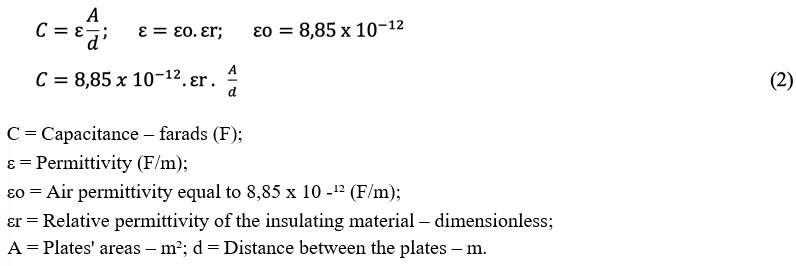
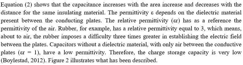
Appendix A – Capacitance Map